Building circuitry for a small robot swarm
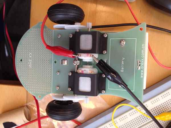
The quest for a simple swarm has brought us 10 assembled Arexx frames.
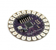
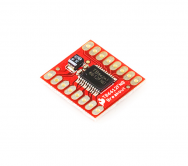
We do not require anything sophisticated. An Arduino board with a tiny microcontroller is already enough. Sparkfun also provides motor controllers, so nothing sophisticated using H-bridges is required anymore. The motor controller handles both DC motors and has a current handling capability of 1 A for each side, more than enough for our bots, that do not typically exceed 70 mA while running.
Our basic idea is to include inductive charging platforms to allow the bots to charge their batteries. We have bought these game-controller battery packs plus charger a number of times, including one of a different form just for variety.
To control the movement of the bots we use this (fig 4)

To detect trouble it is useful to know if the motors are running smoothly or are being blocked, or maybe running without any friction, as this can prompt the bot to change its behaviour if the current strategy does not yield the required result.
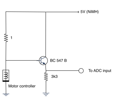
After surfing the web to learn which solutions are available to do this (http://ww1.microchip.com/downloads/en/AppNotes/00894a.pdf) the following circuit has emerged which primarily excells at being very cheap with parts that everyone that has built any electronics whatsoever probably already owns. If not, Velleman (a Begian firm) has a standard set of parts available in shops and on the internet.
The diagram is shown here:
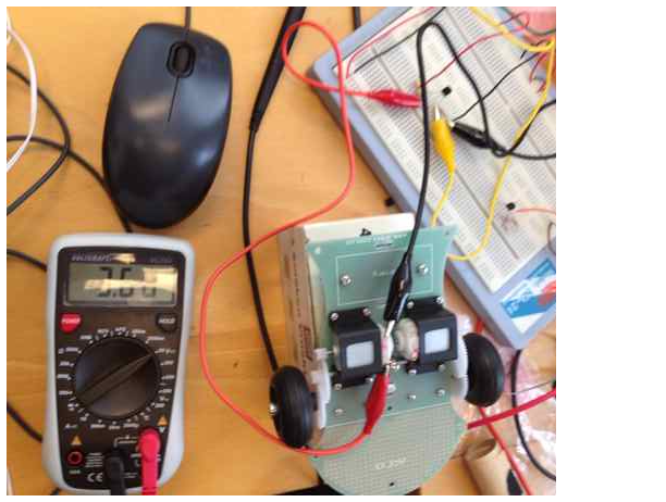
Here is a picture of the test setup 8-)
As could be expected a circuit that simple did surprise us with a few quirks. First of which was that the voltage drop observed in the testbed did not manifest itself in the prototype. The swing, originally from 2.3 to 4.4 Volts, only showed 3.1 to 4.3 Volts, with a lot of noise present in the sample data.
A little test with a potentiometer and a reference voltage showed very stable results, so a more elaborate test setup was built including the motor controller this time.
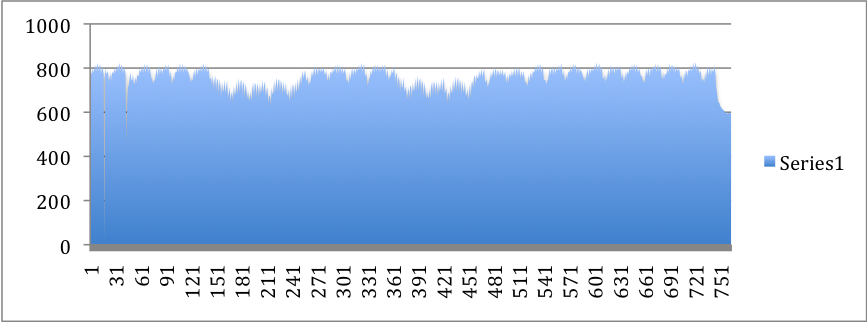
This diagram shows the results coming from the adc input of arduino, and the noise is quite apparent. The lower generic level is measured when the one motor is blocked.
blog comments powered by Disqus