Moway Robot Disassembled
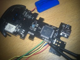
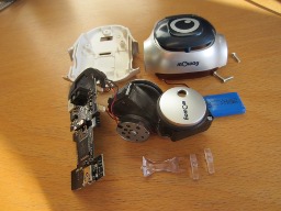
One of the Moway robots ended up on my desk, an ill fate for the poor thing, but a nice moment for me! The Moway robots can be programmed with nice little programs using the GUI delivered by Moway itself. We are of course interested in writing code on a lower level, so we can just upload our C programs that we have lying around. The Moway looks like a computer mouse, it has two round wheels, some LEDs, a USB connector, a flat 3.7V LiPo battery and a Microchip processor, the PIC18F87J50. You can see the robot disassembled in the picture.


As you will immediately recognize, the poor thing is on the operation table. It turned out to be the case that using the Linux facility “picprog” which should be able to upload a new hex file to the robot was indeed able to program something on the robot. Regretfully, it turned out to be some essential parts in its tiny little memory. The Moway was not accessible anymore via USB. By the way, as always in Linux, the way to make something recognized by the operating system is by adding a “udev” rule:
cat /etc/udev/rules.d/52-moway.rules

# Moway rules
SUBSYSTEMS=="usb", ATTRS{idVendor}=="04d8", ATTRS{idProduct}=="003c",MODE="0666", SYMLINK+="ttyUSB%n"
PICkit
 Thanks to the superb support staff at Moway this was
not the end of the robot (yet)! The Moway has 5 pins at the right-side of the
PIC chip. The support stuff was kind enough to provide the pin layout to
revive the robot. From top to bottom: a.) VSS, b.) PGC, c.) PGD, d.) MCLR’,
e.) VDD. A PICkit 2 programmer can be bought for under a 50 bucks at
microchip. The pin layout of the PICkit goes from
triangle on: 1.) MCLR’, 2.) VDD, 3.) VSS, 4.) PGD, 5.) PGC and the 6th doesn’t
need to be used. It is perfectly fine to power the chip from the LiPo battery,
so the VDD you don’t need to connect. You can download the software to use the
PICkit from microchip, the flash utility is called pk2cmd. One of the first
commands you likely want to try out, is pk2cmd -I -P. Don’t do this, it will
try to discover which device you attached to the PICkit 2 debugger, but in
that process it will use higher and higher voltages for the different PIC
families. It is much safer to use the device type if you know it:
./pk2cmd -I -Ppic18f87j50
Regretfully in my case the device does not respond properly:
Device ID = 0000`
Revision  = 0000`
Device Name = <no device>`

Operation Succeeded`
This does not look good!
Logic analyser
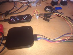
Time to get another fancy gadget in the spotlight, the Logic Analyser from Saleae. This neat small form factor device can sample up to 16 channels with a frequency of up to 100 MHz. The results can be seen in the following screenshot

You can see that all channels seem to do what they are supposed to do. The VDD is on a level of 3.7V, and there seems some data clocked back and forth. The only thing left to do now is to check if we need some additional circuitry to be able to program with PICkit 2. There are some rumours that the PICkit 2 needs some pins like MCLR’ with a pull-up resistor (which might not be necessary when using other programmers). So, we have to wait on the final word from Spain. One thing is for sure, regardless if this specific robot can be revived, the support from Moway has been excellent!
blog comments powered by Disqus
