What is this SLAM?
SLAM (Simultaneous Localization And Mapping) tries to answer two key questions in Robotics:
- Robot Localization: “Where is the Robot?”
- Robot Mapping: “What does the world around the Robot look like?”
SLAM can help you solve the problem of building up a map within an unknown environment (without a priori knowledge), or to update a map within a known environment (with a priori knowledge from a given map), while at the same time keeping track of the current location of the robots in the environment.
Some possible SLAM applications
- Oil pipeline inspection
- Ocean surveying and underwater navigation
- Mine exploration
- Coral reef inspection
- Military applications
- Crime scene investigation
- Earthquake surveillance procedures
Requirements
In order to implement SLAM, you need a mobile robot and a range measurement device, such as a laser scanner, a sonar device or a camera (visual SLAM).
How to implement SLAM
The goal of the SLAM process is to use the data obtained by the robot’s ranging sensors in order to update the position of the robot and the map of the world around it. A very basic localisation process consists of a numbers of steps:
- Move
- Estimate position (odometry)
- Sense features
- Map and localization update
This is indeed a naive approach, because robot odomety of an unknown environment is very error-prone and the result of such an approach would be an inconsistent map. Therefore as an corrected version, SLAM uses a probabilistic approach consisting of the following steps:
- Move
- Predict position (odometry)
- Sense features
- Recognize landmarks (data association) ⇒ loop closure
- Correct position (probability theory)
In this new approach, the ranging sensor data and odometry data are combined to correct the perception of the robot about its location and the position of environmental feature.
This prediction and correction process is described with the aid of some figures below:
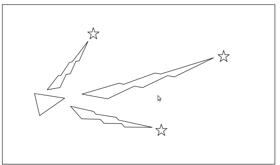
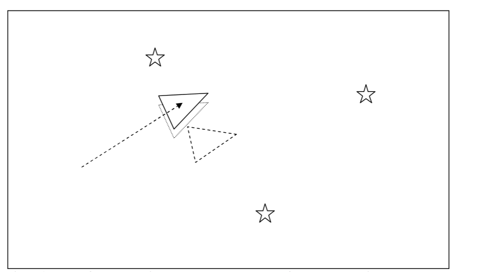
In the figures, the robot is represented by the triangle. The stars represent landmarks (environmental features). The robot initially measures the location of the landmarks, using its sensors (sensor measurements illustrated by the ‘lightning’).
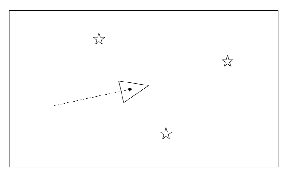
The robot moves. Based on robot odometry, the robot thinks that is it located here.
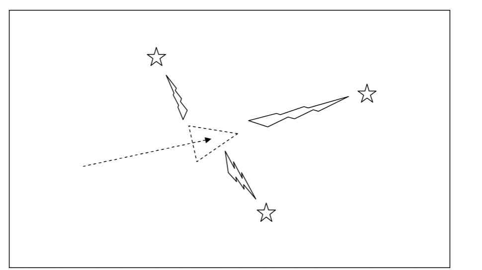
Once again the robot measures its distance to the landmarks using its range measurement sensors. What if the odometry and sensor measurements don’t match? The answer is: The robot is not at the location where it thinks it is (odometry error).
The robot has more trust in sensor data than in odometry. So, the new location of the robot considering the landmarks distances is here. (The dashed triangle is where the robot thought it was using the odometry data).
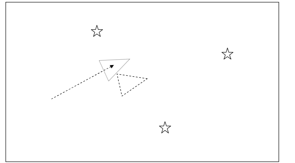
The actual location of the robot is here. You can see that the sensors are not perfect but their measurements are more reliable than odometry. The lined triangle is the actual position of the robot, the dotted triangle is its estimated location based on the sensor data and the dashed triangle is its estimated location based on odometry.
Visual SLAM
At DoBots we are mostly interested in projects involving Visual SLAM, where the range measurement sensor is simply a camera. Using camera as range measurement device has some advantages such as:
- It is fast.
- It has longer range than many other sensors.
- The sensor data contains more information about the environment rather than the distances.
The basic procedure of Visual SLAM is described in the following figures:
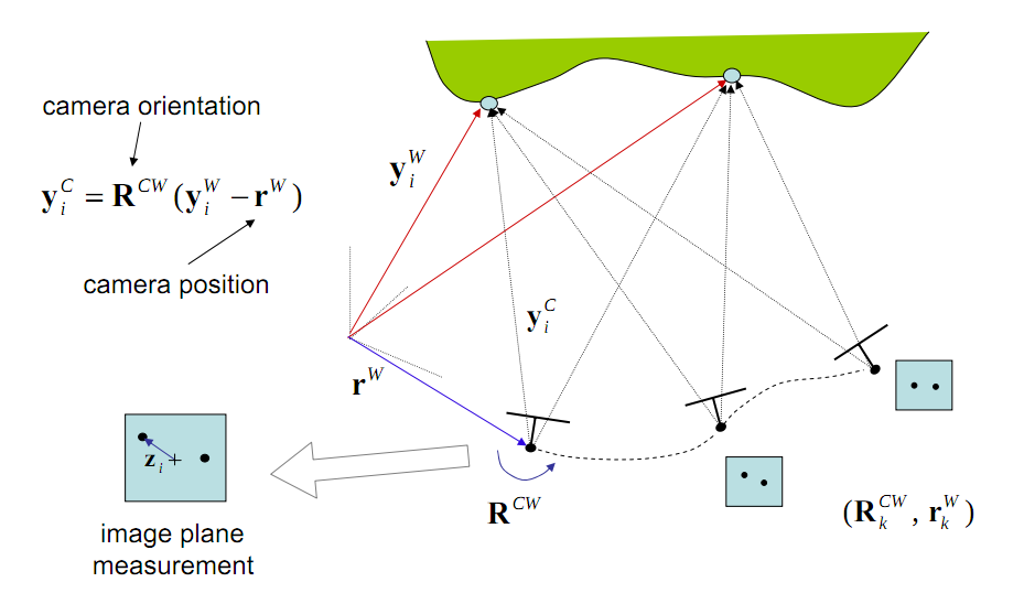
The camera localization depends on three parameters: camera orientation and camera position (which are given by odometry) and the range measurements (which is provided by the camera). The yiW
is the camera distance from the landscape from measurement .
Predictor-Corrector
At any moment(t) the robot localization can be predicted by the robot location at(t-1), the robot orientation and the robot position. This prediction will be corrected by the aid of range measurements as it is shown in below figure:
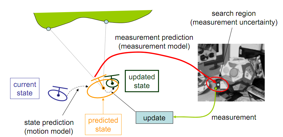
Three stages of the SLAM(Prediction, Observartion and Update) need to be done based on a recursive algorithm which can derive the Robot state from the noisy sensor data. One the best known algorithms which is implemented to solve the SLAM problem is Kalman filter.
In the following links you can see some SLAM projects realization, done by different research groups.
Videos
The following YouTube videos give a nice insight into using visual SLAM:
References
- Visual SLAM (2007), Andrew Davison, Andrew Calway, Walterio Mayol, BMVC 2007 Visual SLAM Tutorial
- Simultaneous Localization and Mapping: Part 1(2006), Hugh Durrant-Whyte and Tim Baile, IEEE Robotics & Automation Magazine, P 99-108.
- Simultaneous Localizatioand Mapping – SLAM (2005), Andrew Hogu, York University, Toronto, Ontario
- SLAM for Dummies: A Tutorial Approach to Simultaneous Localization and Mapping, Søren Riisgaard and Morten Rufus Blas.
blog comments powered by Disqus